Featured Stories
-
Methods to Precisely Measure Tension and Web Control
How to Control Automatically Within Set Parameters -
Measurements Verify Static Control Performance
One can verify that static dissipaters are functioning properly by making verification measurements. -
Three Common Types of Coating and Laminating Defects and the Methods of Inspection to Catch Them
You're close to securing a new contract and the client wants to know more about your quality control processes.
News | New Products
-
BakPac Breaks Records in UK Flexible Packaging
Independent UK pouch manufacturer BakPac, has hit a major production milestone, converting and shipping over 1 million digitally printed stand-up pouches in a single week
-
75th Anniversary Contribution Supports Global Organizations Advancing STEM, Environmental Stewardship, and Social Impact
Michelman is fulfilling its 75th anniversary pledge through a global philanthropic initiative that reflects the company's Legacy of Giving Back.
-
Neopac Wins Two Tube of the Year Awards from the US Tube Council
Voltaren Polyfoil® Tube, produced on Neopac’s new U.S. tube line, receives top honors for seamlessly combining patient-friendly features with aesthetic appeal.
-
Double E Group Unveils the RollMover™ EZX: The Next Evolution in Roll Handling Technology
Double E Group, a global leader in web handling, converting and material handling solutions, proudly introduces the RollMover™ EZX
-
Pulse strengthens market presence with new structure and fresh look
Pulse, the manufacturer of narrow web ink solutions for label and packaging printers, has announced strategic promotions designed to support the company’s growth objectives.
-
Martin Automatic at Labelexpo
Martin Automatic will showcase two of its industry-leading MBS automatic unwind splicers at Labelexpo Europe 2025
-
FPA Updates Annual Flexible Packaging Buyer's Guide
The Buyer’s Guide is a key reference resource for the flexible packaging industry
Expert Advice
Static Beat | Static Dissipator Locations
- Published: September 18, 2014, By Kelly Robinson
 Static must be controlled sufficiently to suppress sparks. Static charges on plastic and paper webs cause sparks that can ignite flammable solvent vapors and shock operators who must handle the wound rolls. These sparks also deposit spots of charge that can cause cut sheets to stick.
Many static dissipators are commercially available. Passive dissipators, such as static brushes, grounded pin arrays, and tinsel, can reduce a high level of static charge to a low level. And active static bars can reduce the static level to essentially zero. Excellent technology for dissipating static charge is available. The challenge is to install dissipators in the right places so that sparks are suppressed.
When identifying locations for static dissipators, think in terms of RISKS and COUNTER-MEASURES. Use the two-step process in Figure 1 to identify locations for your static dissipators. The first step is to identify areas at RISK from static sparks, such as C1D1 solvent areas and winding rolls. Any area of the process where sparks could cause injury, downtime, or product quality problems are RISKS. Our “Inner Circle” static dissipators are be installed to suppress sparks in RISK areas.
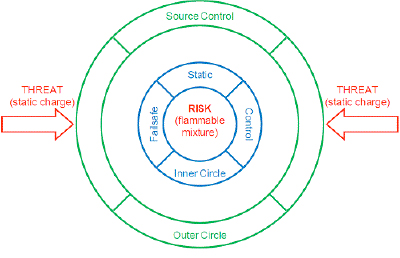
The second step is to identify charging sources using a static survey. Use an electrostatic fieldmeter to measure static on each accessible web span. The electric field on the web span exiting a particular roller or process that is a charging source is significantly higher than the electric field measured on the entering web span.
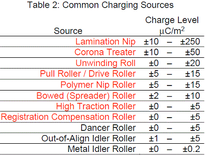
Common charging sources in Table 2 listed in red deposit enough static on a web to cause sparks. Sources that deposit ±5 μC/m2 of static charge cause the electric field to increase by ±6 KV/cm and sparks can occur. Our “Outer Circle” static dissipators are installed to dissipate static from each source of static charging.
RISK areas in Figure 3 are protected by “Inner Circle” static dissipators and static from each charging source is dissipated by “Outer Circle” dissipators. With static dissipators installed in these locations, our RISK areas are protected from static charge THREATS by a fault tolerant static control system. The failure of any single dissipator (Fault) is insufficient to expose the RISK to a THREAT.
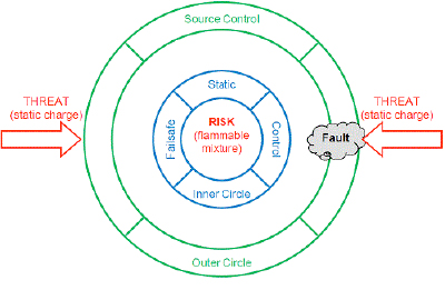
Commercially available static dissipators have excellent performance. Our challenge is to install these static control devices to suppress sparks in RISK areas of our process. Static dissipators should be installed “best practice” locations to protect RISK areas with a fault tolerant static control system so that any single failure or fault is insufficient to expose a RISK to a static THREAT.
I invite you to ask questions about this column and to suggest future topics. My email address is: Kelly.Robinson@ElectrostaticAnswers.com.
Static control expert Dr. Kelly Robinson, president of Electrostatic Answers, has 27+ years of experience in problem-solving and consulting. Kelly writes PFFC's Static Beat column and the Kelly on Static blog. Contact him at 585-425-8158; kelly.robinson@electrostaticanswers.com; www.electrostaticanswers.com.


