


Roll Diameter Requirements in Converting Processes
- Published: July 01, 2019
By Bill Gilbert, Siemens Corporation
Common Methods of Diameter Determination
Diameter determination can be accomplished either by direct measurement from an external sensor or calculated from process data in the tension control. The following two methods are the most common methods for obtaining a diameter by measurement.
Lay-on Roll Diameter Measurement
This method consists of a pivoting arm that contacts the outside diameter of the roll with a wheel or an idler roll. The pivoting arm is loaded against the roll and a sensing device is mounted to the pivot point. The measured angle from this sensor is then converted to the roll diameter. The sensing devices can be a rotary potentiometer, analog proximity sensors, hall-effect sensors or rotary pulse encoders.
Advantages:
• Simple and robust;
• Relatively low maintenance and
• Diameter value does not require spindle or web motion.
Disadvantages:
• The roll or wheel must contact the roll, an issue for materials that cannot have surface contact;
• The Lay-on Roll mechanics can interfere with roll changing or machine maintenance;
• Out-of-round rolls cause inaccurate diameter readings;
• Mechanical system, and will require some maintenance, affects machine design;
• May limit the roll size on the machine;
• The sensor output is rotary and not proportional to diameter, the angle must be transformed to a linear distance.
• Must be loaded against the roll (pneumatic, other force); and
• The output signal may require filtering.
Diameter Sensor Measurement
The diameter sensor measurement makes a linear distance measurement of the roll diameter. Typically this sensor is an ultrasonic device, but optical and laser sensors can be used. In the case of the ultrasonic sensor, it emits a signal that travels to the rolls surface, bounces off and returns to the sensor. The distance then is a linear value proportional to the radius of the roll. This method is typically used for establishing starting diameter.
Advantages:
• Provides a linear output proportional to roll diameter;
• No material contact with the roll;
• Outputs can be connected directly to the drive or controller; and
• The diameter value does not require motion.
Disadvantages:
• The measurement can be affected by moving air and temperature drift (ultrasonic);
• The measurement will be affected by objects between the roll outer diameter and the transducer;
• May need periodic maintenance and calibration;
• Susceptible to dirt and dust;
• Certain low density materials may absorb the ultrasonic signal;
• Mounting is critical and if the sensor is disturbed it will not operate properly;
• Prone to damage from roll changes;
• Typically does not work well with out of round rolls; and
• The output signal typically requires filtration.
Measurement techniques can be used for providing a starting diameter reading but neither of the measurement methods are practical for providing a satisfactory running diameter to the tension control system. Running diameter determination is best accomplished through a calculation of the existing process data. The following two calculation methods are the most common means of obtaining a roll diameter by calculation of machine data.
Web Velocity / Winder Shaft RPM (V/n) Calculation
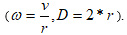
Web Velocity / Winder Shaft Rpm (V/n) is the most common method of determining continuous or running roll diameter for center driven spindles. In this method of calculation, diameter (D) is determined by using the relationship between surface web velocity (V) and angular velocity of the spindle (W) using formulas.
This method can provide reliable, steady state, diameter values, but because only instantaneous velocity values (samples) are used in the calculation, the diameter result of this mode will not be as accurate while accelerating and decelerating. The use of a diameter holding circuit is required below a determined minimum speed.
Advantages:
• Requires no additional machine hardware;
• The calculation is simple and directly proportional;
• No contact to roll issues; and
• Provides acceptable steady state diameter status.
Disadvantages:
• Must be above minimum line speed for calculation;
• Filters required for output smoothness;
• Filter changes may be required for changes in material thickness (fast diameter changes);
• Poor accuracy during acceleration and deceleration; and
• Requires a minimum speed setpoint and diameter hold.
Roll Turns and Web Thickness Calculation
Counting Roll Turns and adding increments of web thickness can be the most accurate method of all the previously discussed methods; however this is highly dependent on very closely meeting multiple criteria. This method counts the incremental addition of the spindle revolutions and adds a unit of the web thickness for each revolution.
Diameter New = (Diameter Old + (Thickness *2))
The determined accuracy depends on the accuracy of the web thickness input variable and the ability of the system to maintain roll hardness and limit air entrapment. If all conditions are met, counting roll turns can provide a stable diameter value regardless of speed. This method is typically used with metal webs or foils that have a precise thickness and have no issue with air entrapment between layers.
Advantages:
• Can be the most accurate calculator;
• Not susceptible to acceleration / deceleration / speed disturbances;
• Does not require filtration; and
• Does not require a diameter hold.
Disadvantages:
• Open Loop System;
• Can require a rider roll to eliminate air entrapment;
• Web thickness variable must be accurate; and
• Requires a very accurate starting diameter.
Improved Methods of Diameter Calculation
An improved method can be applied to most tension control systems and offers several benefits over the previously discussed diameter determination methods. There are two possible adaptations of the method; the first uses the integral of the web velocity and the winder rpm (calculated position) and the second performs the same calculation with a measured actual position.
Integration of Web Velocity / Spindle RPM Diameter Calculation
In this method of diameter calculation, velocity is integrated over time to determine the linear position of the web and angular displacement of the spindle.
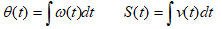
Then diameter is calculated based on web distance (S) and angular displacement (0) .
The positions used in the calculation are updated at a predetermined number of spindle revolutions. Interpolation is then done between the old and new values. Calculating with a web length and a spindle angle provides an increased stability of the measurement and does not require the filtering that is used in v/n. The added stability of this method is especially seen during acceleration and deceleration. The added stability of this method is especially seen during acceleration, deceleration and at standstill. In addition the diameter hold is not required.
Advantages:
• More accurate than (v/n) during acceleration / deceleration / speed disturbances;
• Does not require filtration;
• Can be used to also determine starting diameter (actual position mode); and
• Diameter hold not required.
Disadvantages:
• Integral update time must be fast; and
• Can be improved upon by using actual positions.
Actual Web Position / Actual Spindle Angle Diameter Calculation
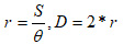
Motion controllers and some drive control systems can provide the actual positions of real axes. These systems can implement this method by using the actual position of web and roll providing even greater accuracy in the diameter determination. With position based diameter calculation, position is measured directly from spindle and web displacement and diameter is calculated directly using formula.
Performance of the Diameter Calculation Methods
Comparing the Calculation Methods
In order to analyze and compare drive based diameter calculator methods, two factors need to be considered:
1. Constant speed operation vs. acceleration profile; and
2. Update frequency of the diameter calculator logic.
Material velocity over winder shaft diameter (V/n) calculation takes discrete snapshots of web and spindle velocity with no filtering of the signal built-in to the calculation. The signal is expected to vary during operation both at constant speed and during acceleration shown in actual measurements, Figures 10 - 12.
As an improvement, Integral method of calculation provides transient response filtering by integrating velocity over the period of time. That produces a more stable and accurate signal, as compared to V/n. If velocity remains constant, the accuracy of the integral diameter calculation is comparable to the position based calculation (see Figure 10). During acceleration, when the velocity is constantly changing, the integral diameter calculator effectiveness is reduced. Increasing the sampling rate of the integration function increases the accuracy of the approximation of the actual position displacement.
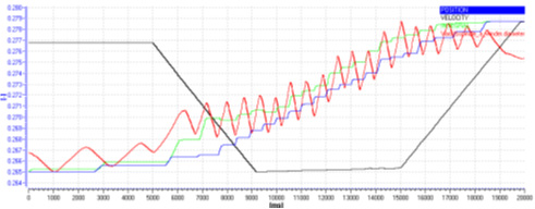
Figures 11 and 12 demonstrate the effect of increasing the velocity sampling rate from 1ms to 6ms during acceleration on the actual machine. While at 1 ms, the integral performance is roughly identical to position based calculation: the 6ms trace shows integral calculation deviation during acceleration phase of the profile.
Figure 10: Diameter Calculator: Constant Speed, 1ms update time
Web Velocity: 100 m/min
Update time: 1 ms
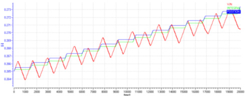
Figure 11: Diameter Calculator: Acceleration, 1ms update time
Acceleration profile:
1. 50 m/min
2. acceleration to 300 m/min
3. deceleration to 10 m/min
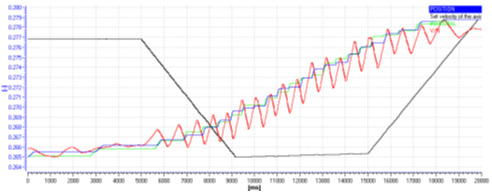
Figure 12: Diameter Calculator: Acceleration, 6ms update time
Acceleration profile:
1. 50 m/min
2. acceleration to 300 m/min
3. deceleration to 10 m/min
References
[1] William Gilbert, “Methods of Diameter Determination”, AIMCAL AWeb Handling Conference, 2006
[2] Denis Morozov, “Optimizing Tension control in Center Driven Winders”, AIMCAL Fall Conference, 2012
About Siemens USA
Siemens Corporation is a U.S. subsidiary of Siemens AG, a global powerhouse focusing on the areas of electrification, automation and digitalization. One of the world's largest producers of energy-efficient, resource-saving technologies, Siemens is a leading supplier of systems for power generation and transmission as well as medical diagnosis.