


Web Lines | Action Plan for CD Buckles, Part 2
- Published: April 11, 2017, By Tim Walker
Mechanisms, descriptions, and remedies for your cross direction buckles.
In Part 1 of our Action Plan, we looked at the reasons why cross direction buckles form. In this second part of a three-part series, you’ll find remedies for CD buckles, starting at the core and moving outward.
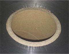
Mechanism 1: Core collapse, core crushing
Description—When the pressure on the core exceeds its buckling strength, the core buckles and the layers of the roll follow.
This is analogous to constructing a multi-story building on swamp land.
Remedies:
- Wind on a core with high stiffness (resistance to compression from buildup of roll core pressure).
- Reduce the pressure exerted on the core with low starting tension, more taper tension, less winding nip load, limiting roll buildup, decreasing stack modulus, or winding on larger cores.
- For paper cores, ensure cores have low moisture content to avoid shrinkage after winding if stored in relatively drier environments.
- Ensure that core shaft or chuck expansion does not significantly change core dimensions when they are removed.
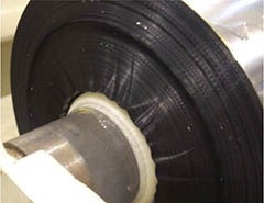
Mechanism 2: At-core CD buckles from soft start
Description—If cores are stiff relative to the winding roll, CD buckles may be caused when the initial layers of a winding roll have low tension, wrinkles, or misalignment buckles (i.e., bulges from shifting of the roll’s first layers) and are subsequently compressed by the pressure of the wound roll.
This is analogous to constructing a multi-story building with a poorly design first floor.
Remedies:
- Ensure the initial layers of the winding rolls are especially tight and free of wrinkles, misalignment, core scrap, of excessive entrained air.
- Use zero-speed splicing to improve well-aligned, wrinkle-free roll starts.
- Use at-speed turret winder with minimum wrinkle transfer mechanics, such as stationary knife or independent arm winders.
- Ensure the winding nip (a.k.a. lay-on, pack roller) makes uniform contact with the core through good alignment and freedom of movement. For ‘hard’ rolls (films and foils), use a compliant nip roller (30A-45A Durometer, ¾ to 1in. thick). Minimize core eccentricity.
- Allow the winding nip roller to self-aligning to the winding roll to avoid excessive air or lack of nip-induced tension of uneven contact (*This recommendation had mixed support. Winder suppliers say, “You can’t fix product profile problems at the winder.”)
- Avoid imperfections in the core and core surface. The step change of the initial layer or core tape can be enough to determine where the buckling occurs.
- Check and minimize core and winding nip deflection.
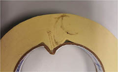
Mechanism 3: Near-core buckled layers
Description—The layers immediate near the core are buckle-free, but CD buckles form within a few layers off the core.
Think of a winding roll as having two cores. The first core is the paper, plastic, or metal cylinder that defines where winding will begin. The second core is formed by the initial layers of the product wound near the core.
The layers nearest to a stiff core will see minimal radial losses and remain in MD tension. Layers away from the core fall when those below them compress. In CD buckles, the early layer compression is greater on a percent basis than outer layer initial strain.
Remedies:
- Wind on a larger cores. Any radial changes have smaller effect at larger diameters. Larger cores are stiffer, given similar thickness and material.
- Wind with less total layers (difference in final and core radius divided by thickness).
- Ensure high tension in initial layers from torque and nipping.
- If tapering tension and nip load, consider tapering with a hyperbolic profiles (i.e., the rate of taper varies with roll buildup, with greater rate of decrease near the core than in the roll’s outer layers). Alternately, use a ‘hard’ start profile where tension or nip load is held high in winding the initial layers (0.1 to 0.5 in.) before the taper function begin.
- For zero-speed transfer winding, avoid speed-based taper functions that decrease tension during low speed layers added during initial acceleration.
- Avoid loss of tension at roll start from tension control losses, accelerating inertial torque, uneven nipping, or winding geometry changes.
In Part 3 of this series, we’ll look at more remedies for these CD buckling defects, moving outward from the core.
Web handling expert Tim Walker, president of TJWalker+Assoc., has 25 years of experience in web processes, education, development, and production problem solving. Contact him at 651-686-5400; tjwalker@tjwa.com; www.webhandling.com.