


Avoiding Thermal Runaway in EV Batteries
- Published: October 09, 2023
By Matt Fyffe, General Manager, Meech USA
Electrification of our society is accelerating. EVs, scooters, domestic appliances, domestic energy storage and green energy storage banks are all examples of this trend and new lithium-ion battery technology is having to advance at the same pace to make it all possible.
As this industry rapidly ramps up, there is a critical need to deliver battery components with zero contamination at each production stage, to help avoid the risk of thermal runaway downstream during the operational life of the battery.
Lithium-ion Batteries and Thermal Runaway
The smallest unit of a lithium-ion battery is the cell, which comes in three principal form factors: Prismatic, pouch and cylindrical. In some electric vehicles, there can be up to 7,000 cells making up the battery pack, depending on the vehicle size and range.
Each of these cells are made up of an anode and cathode — separated by an essential insulative film, which prevents physical contact between the anode and cathode, while also crucially facilitating transportation of ions in the cell. Designers and manufacturers need to find the balance between mechanical robustness and effective porosity and transport properties. Any damage or weakness in the separator film has the potential to lead to an electrical shortage.
Under normal working conditions, the polymeric separators heat up and can sustain variable operating temperatures depending on the material and structural design. However, in the rare event that an electrical short occurs, chemical reactions can supersede the normal electrochemical processes (ion and electron flow) and more heat is generated than can be dissipated.
The short can very quickly accelerate, leading to ‘thermal runaway,’ meaning the battery can no longer be controlled and can become a potential fire and safety hazard. Whilst these instances are few and far between, even a small number of incidents can be incredibly damaging to individual brands and to the overall public perception of battery technology as more and more people consider adopting electric vehicles.
The recognized wider causes of thermal runaway are: Abuse (heat, crush, penetration), overcharge and defects (including contamination) in the cells.
Contamination
 One of the least understood causes of thermal runaway is due to manufacturing defects caused by contamination within the cells. As there are no universal standards in place, the in-built designs and manufacturing processes across multiple machine suppliers need to consider where contamination can occur and how to ensure dangerous inclusions can be avoided.
This is not an easy process as this is often outside of the battery designers’
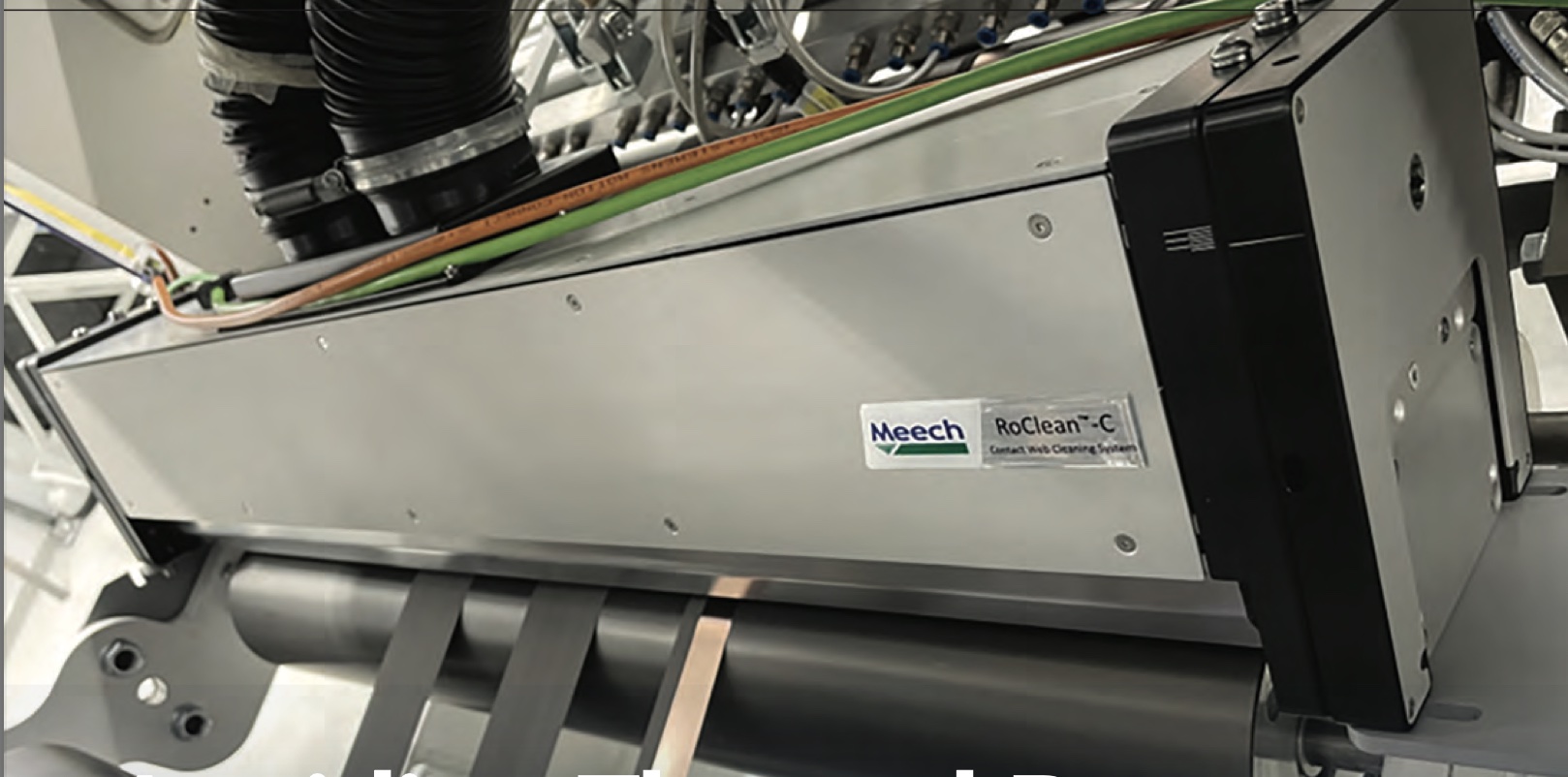
and machine builders’ core competence and expertise. There are a number of primary contamination risk areas... Pre-coating (maintains coating quality and layer thickness) — Thickness and quality of the coated web is essential (to maintain a uniformed structure within the EV battery). Any contamination within the coating would affect the performance within the structural layers and would be carried forward into the final construction. Prior to the coating stage of the copper/aluminum web, the use of a web cleaner on the substrate can remove surface contamination.
Coating roller cleaning (maintains coating quality and layer thickness) — Another contamination risk area in the coating process is the roller itself, which guides the web very accurately to the substrate coating. Either non-contact type (dynamic air flow), or a specialist abrasive brush contact type cleaner (combined with air flows) can be used. These will remove contamination to ensure there is no transmission to the underside of the web (so there is also no impact on coating thickness).
Pre-calendaring (maintains coating) — During this stage, the web and coating layers are compressed together to the exact required thickness, which also ‘activates’ the coating on the web itself. Cleaning prior to this critical stage prevents contamination being trapped in the coating, which could result in the coating layer being out of tolerance. Similar to the coating roller, the calendaring rollers may also need cleaning.
Post-slitting (reduces risk of soft electrical shortages) — The slitting process can create a lot of debris made up of a combination of ‘base material’ and ‘coating material.’ This is a high contamination risk stage where cleaning is imperative to avoid the risk of future electrical shortages and expensive rejects.
The use of a web cleaner at this stage ensures that the particles are removed from the surface of the web and filtered away from the operating atmosphere to avoid recontamination. Depending on the process and materials, contamination can be bonded or unbonded requiring careful analysis to choose the optimum contact or non-contact web cleaning solution. Slitting dust is highly likely in this area and, as some coating materials have toxic content, special consideration is needed.
Post Cutting/Stamping/Laser Cutting of Electrodes (reduces risk of soft electrical shortages) — Like the post-slitting stage, during electrode cutting, particles and debris can contaminate the web. To avoid this, web cleaning at this stage will clean the surface of the substrate, leading to clean and clear separation layers. The same considerations apply around toxic dust removal and containment to respect the clean room environment and operator safety.
Static Control on Separator Film (reduces risk of soft electrical shortages) — The porous membrane must be placed between electrodes of opposite polarity, and it is permeable to ionic flow but crucially prevents electric contact of the electrodes. The separator film is very sensitive to static charge created by winding, unwinding, friction on rollers, throughout the transfer processes.
Static charges generated on insulative materials such as the separator film attract ambient particles adding to contamination risk problems.
In extreme cases, if charges generated are high and not carefully controlled then small sparks may result leading to small ‘dendritic burns’ in the material. While not immediately obvious, these can lead to a loss in insulative properties and create shortages in the battery cell itself. In soak tests or in final vehicle use these would show up as a loss of capacity or over heating problems.
Throughout the separator film transfer, ionization bars should be located close to the film where charges are measured. Close range DC type bars can be ‘tuned’ to match the material and application to ensure rapid charge decay times and minimal residual charges are achieved. Most modern ionization technology is available in formats that suit short, medium and long-range applications.
Evidently, due to the complexities of cell manufacturing — be that based on lithium-ion
or hydrogen fuel-cell technology — there are many processes where either static or contamination can build-up resulting in wide-reaching detrimental effects on the battery’s performance and safety, not to mention, profitability and market success. Manufacturers should consider static control and web cleaning equipment to minimize the risk of thermal runaway.
About the Author
Matt Fyffe joined Meech Static Eliminators USA in 1994, starting in the role of marketing coordinator and inside technical sales. Since then, he has been involved in such areas as production and quality control, sales management and operations management. He was appointed General Manager in 2001 with responsibility for day-to-day operations of Meech USA and the development of Meech business throughout North, Central and South America.