


An In-Depth Look at Extrusion - Part 1
- Published: September 12, 2018, By Christine Pietryla Wetzler
BACKGROUND
Extrusion is simply defined as the forcing of a liquid through a die. In modern industrial terms, extrusion is the pumping of a liquid through a die to yield the final shape desired. The liquid forced through the die can be a polymer or a metal, such as molten aluminum. This series of articles will focus on extrusion of polymers through flat or round dies.
Extrusion, as we know, is today is more than 100 years old. Early extruders were used to extrude rubber, an elastic material. As material development progressed, synthetic viscoelastic materials were developed for extrusion. These materials behaved differently, and the extruder was modified to accommodate these new materials. Original rubber screws utilized constant depth/variable pitch to compress the rubber material, versus screws for polymers, used variable depth/constant pitch to provide the compression necessary to generate pressure.
The machine used for extrusion is not surprising called an extruder. Extruders are complex machines which consist of the following components:
- A motor
- A drive system to control the motor
- A gearbox
- An extruder barrel
- An extruder screw
- A system for heating and cooling various extruder components
- A feed system to introduce plastic pellets into the extruder barrel
- A filtration system, including break plate and screen changer
- A die
- Instrumentation such a temperature, pressure, and thickness measurement
- Various ancillary equipment such as coextrusion, ozonizing, corona treating
This series of articles will focus on traditional single stage, single screw extrusion without the use of a gear pump. If questions arise on twin screw extrusion, extruder venting, etc., these issues will be addressed.
PROCESS OVERVIEW
The configuration of an extrusion line depends on whether there is a substrate or not. Figure 1 below shows the essential components of a blown film line, including the extruder, die assembly, automatic air ring, and bubble cage. The rotating tower assembly, thickness gauge, corona treater, and winder are not shown. In the blown film process, the extruder or extruders melt plastic pellets and pump the hot, viscous polymer melt into the die, which forms a circular film. As the film exits the die, it is called by an air ring and transported upwards to the collapsing tower, and then onto the winder. Blown film line speeds are typically limited to a few hundred feet per minute (100-200 m/min).

Figure 1. Alpha Marathon 77-layer nanofilm blown film line (Photo by Tom Bezigian)
Cast film lines differ from blown film lines in that the die is flat instead of round, the web is cooled with a chill roll instead of an air ring, and the web is transported horizontally instead of vertically. The two processes yield films with vastly different properties due to the cooling methods and resins used.
Figure 2 below shows a complete small cast film/extrusion coating line, with the unwind stand to the left, the extruder in the center, and winder to the right. Included on this line are all the components normally associated with an extrusion coating line, namely an unwind stand, corona treater, liquid primer, flame treating, coating/casting section,
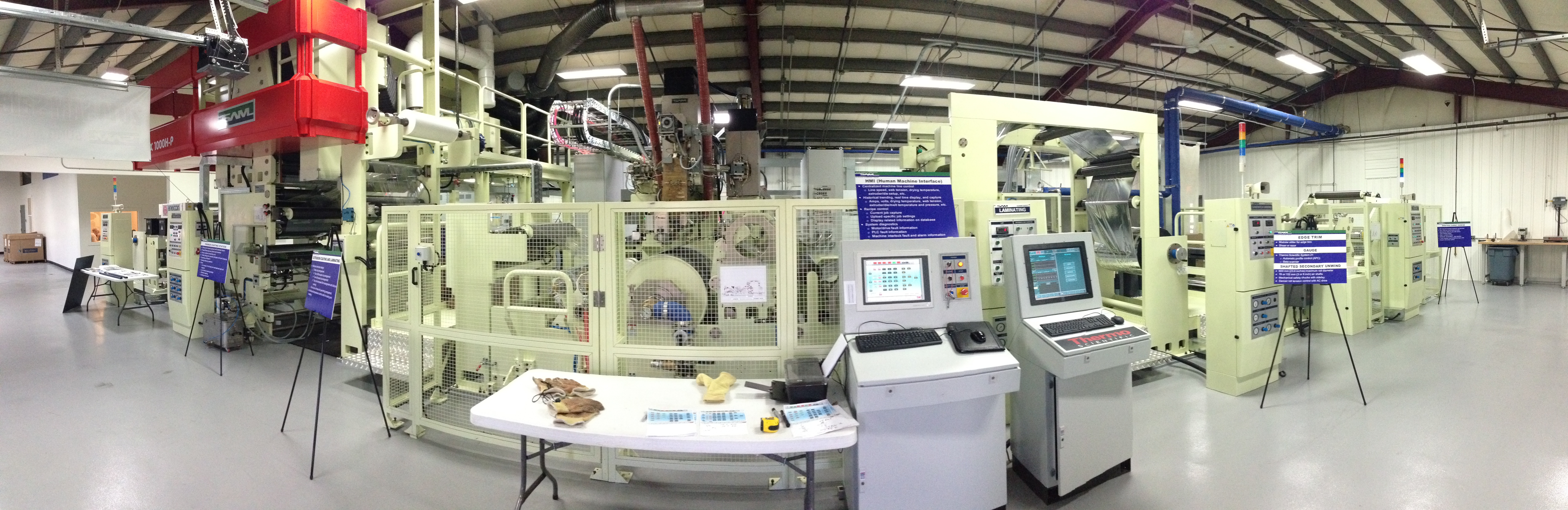
Figure 2. The SAM, NA pilot laboratory in Phoenix, New York (Photo by Tom Bezigian)
Flat sheet extrusion dies are not limited to thin coatings, but can also produce

Figure 3. Extrusion of a 6.35 mm (0.250”) thick 3-layer coextruded ABS sheet out of a 4 meter (10 foot) wide multi-manifold die into a 3-roll calendar stack. The line speed in this process is about 1 meter per minute (3 feet/minute) (Photo by Tom Bezigian)
THE EXTRUDER
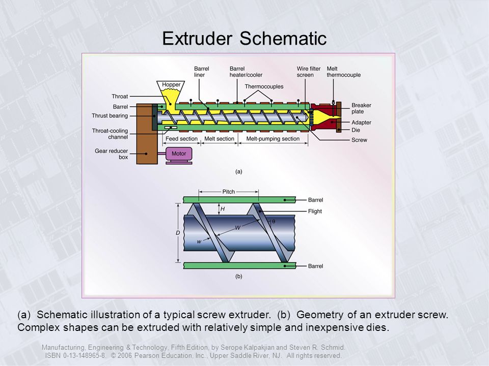
As mentioned early, the extruder has several components, which is depicted in Figure 4 below. All these pieces fit together to yield a salable product. A summary of the process follows.

Figure 4. Extruder Schematic showing major components, from http://slideplayer.com/slide/6557489/23/images/4/Extruder+Schematic.jpg
The extruder motor turns the gears in the gearbox, which is coupled to the extruder screw. Once the extruder reaches operating temperatures, the screw turns and brings the plastic pellets supplied by the hopper into the barrel. The pellets are conveyed forward by the pushing action of the screw flight. The volume of the first flight times the bulk density of the pellets times the RPM gives the output per minute.
As the pellets move forward they encounter a restriction at compression (or melt) section of the screw. In this section, the channel depth (H) of the screw flight diminishes, causing pressure to rapidly increase in this area. The pressure forces the pellet against the barrel wall, where friction between the pellet and the barrel wall increases
As the plastic moves downstream, the average temperature
There is a tremendous energy transfer from the screw to the pellets in the compression zone, and pressure within that zone can easily reach 400 bar (~6,000 psi). The energy to pump and melt the plastic pellets ultimately comes from the extruder motor which is transmitted through the gearbox and the extruder screw. Once the plastic leaves the compression section, pressure generation ceases, and pressure consumption begins. Enough pressure must be generated to convey the viscous molten plastic out of the extruder, through the filtration system, piping, coextrusion adapters and die so that a uniform flow exits the die
I will continue next month on the melting mechanism, extrusion physics, and other aspects of screw design.
Tom Bezigian holds a B.S. in Plastics Engineering from the University of Massachusetts–Lowell. He has been affiliated with the converting industry for more than 30 years and writes a column, Poly Ploys, for PFFC. It focuses on the field of polymers, laminations, and coatings with emphasis on R&D, quality assurance, manufacturing, marketing, operations, finance, and expert witness experience in the blown film, cast film, orienting, extrusion coating, and converting industries. He is the owner of PLC Technologies consultancy with over 30 years experience. Contact him at tbezigian@pffc-online.com.


