Featured Stories
-
Choosing the Right Flexible Packaging Pouching Supplier
Wish you had more production capability to fulfill pouching jobs or maybe you are looking for a backup when your equipment goes down? -
Sun Chemical White Paper: Color Management
Ensuring Color Consistency in Every Corner of the Globe -
Reducing Energy Use and Optimizing Performance Through UV LED Printing
Environmental regulations are increasing pressure on the printing industry to exceed their sustainability goals.
News | New Products
-
PGSF Announces Winner of Fall Box Design Contest
The Print and Graphics Scholarship Foundation (PGSF) has annoucned Audrey Walch as the 2024 Fall Student Box Design Contest winner.
-
FPA Announces 2025 Board of Directors
The Flexible Packaging Association (FPA), the leading advocate and voice for the growing U.S. flexible packaging industry
-
Kampf GmbH Announces Merger of Atlas Converting North America Inc. and Kampf Machinery Corporation
Effective April 1, 2025, the two U.S. locations Atlas Converting North America Inc. (Charlotte, NC) and Kampf Machinery Corporation (Windsor, CT) will operate under the unified company name Kampf Machinery North America Inc.
-
Ashland showcases innovative, environmentally sustainable1 additives for coatings and specialty markets at European Coatings Show
Ashland Inc. is harnessing its innovative technologies as a leader in rheology modifiers
-
interpack 2026 Fully Booked
With just over a year to go, the course has been set for interpack
-
Keypoint Intelligence’s Jeff Wettersten to Lead Packaging Innovation Session at FuturePrint TECH
Jeff Wettersten, VP of Packaging at Keypoint Intelligence, will take the stage at FuturePrint TECH’s Packaging Day on April 3
-
IMFA Announces Annual Conference Speaker Lineup Featuring Huhtamaki’s Ann O’Hara as Keynote
The International Molded Fiber Association (IMFA) has announced its lineup of speakers and sessions for its upcoming Annual Conference in Miami, Florida.
Expert Advice
WEB EXCLUSIVE: Tension Control: Dancer Systems Defined
- Published: April 16, 2009, By By Greg Cober, Warner Electric www.warnerelectric.com
One of the challenges in working with tension control systems is working with closed loop dancers. While dancers are a seemingly simple mechanism, there are complexities below the surface that can impact system performance significantly. This article will define the key parts of a dancer system and how they can interact to provide a system that works well or poorly.
A well-built, well-installed dancer working with a proper control can provide a flexible closed loop means of controlling tension in both unwind and rewind applications.
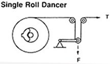
We will use a simple unwind system to discuss the various parts of a dancer system.(Please note that there are many possible dancer designs, but for clarity’s sake, we will restrict our discussion to the simple design in Figure 1.) As a web of material (or strand of wire) unwinds, it passes over a roller, around the dancer roll, and then over a third roller.

The dancer roll is allowed to float (rise/fall) as material feeds into the process. As the dancer roll rises and falls, the tension system is adjusting for minor changes in tension. In most well-designed systems, the dancer roll will rise and fall in small increments constantly. In short… it dances!
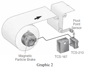
In a closed loop dancer unwind system, there are several key components: the dancer itself, a feedback potentiometer, a control, and the brake or drive. The goal in a dancer system is for the dancer to remain at the mid-point of travel. Pressure on the dancer establishes the tension for the web. The brake in the system controls how fast material is allowed to unwind. Brake pressure changes based on feedback from the dancer potentiometer to the control and from the control to the brake or drive.
If the process is consuming material faster than the unwind is releasing material, the dancer will rise (the loop under the dancer will become shorter). If the process is consuming material slower than the unwind is releasing material, the dancer will fall (the loop under the dancer will become longer).
In the simple dancer system, the dancer can rise and fall 30 deg around its midpoint as changes occur. As this rise and fall occurs, the feedback potentiometer will provide a signal back to the control (as shown in Figure 2).

The control in a dancer system interprets the feedback signal through a PID loop. It looks at the direction of change, amount of change, and rate of change. Based on these three variables, the control will adjust the force at the brake appropriately. A slow change in dancer position will result in a slow change in brake force. A rapid change in dancer position will result in a rapid change in brake force. Adjustments within the control tune the response to the level required by the specific product being manufactured. Some products require very responsive systems, some less so.
Correcting a Range of Conditions
The dancer in the system, as it dances, is correcting for a wide range of conditions. The unwind roll may be slightly out of round with the result being a fast/slow feed rate. There may be mechanical wear issues in the unwind stand, such as worn bearings, alignment issues, and similar mechanical inconsistencies. The material being handled may be highly extensible and prone to stretching. The process itself may have a start/stop function as might be found in a heat-sealing process. Finally, there is an acceleration and deceleration ramp as the machine starts and stops. All of these dynamic conditions, some of which are occurring simultaneously, conspire to change the tension of material being used in the process.
This ability to absorb changes and correct for them within the dancer loop is the great advantage of the dancer system. A second benefit of a dancer system is that the storage loop allows for faster roll acceleration and deceleration and allows for faster splice times than for systems that do not have the same storage capability, such as load cell systems.
Loading the Dancer
For optimum performance, the dancer should be constructed of thin-walled tubing and be loaded by massless, low-friction air cylinders. A rolling diaphragm device is most commonly used. For greatest accuracy, the wrap on the dancer roll should be exactly 180 deg. Anything attached to the dancer for loading will detract from the dancer’s ability to act as a buffer and should be made as light and (in the case of air cylinders) efficient as possible.
A common mistake in loading of dancers is to use simple weights on the dancer arm. The problem with using weights is that as a dancer rises and in the milliseconds before it begins to drop, the inertia of the weight wants to continue upwards. In some systems, this causes no untoward problems, in many it causes error.
Some users will attempt to create the ‘no-weight’ condition by adding counterbalance weights to the dancer. While this reduces the weight at the dancer roller, it leaves mass in place. What can further complicate matters is the ‘helpful’ operator who decides that more or less counterbalance is needed.
An additional method of loading dancers that has less than desirable results is to use springs. For systems where less-than-precise tension can provide adequate results, it is possible to get away with springs. If precision is needed, springs will create a less-than-precise result. As the spring elongates, it will change its effective force. Further, as the spring wears, it will lose effective force.
Dancer System Limitations
The constraints on dancer systems are few but can be significant. Perhaps the primary reason that a dancer would be a poor choice is that the material being tensioned is not flexible or is fragile. A dancer requires the 180-deg turn shown in Figure 1. Not all materials can make that turn without sustaining damage.
A second constraint can be space, especially when retrofitting into an existing machine. There is a wide array of alternative dancer designs to the traditional single-roller design. Some, like the S-Wrap dancer, consume little space. Tension system manufacturers will generally be able to offer an array of designs in their catalogs, websites, or via their applications support department.
The benefit of a well-designed dancer system is that it provides a storage loop where changes in tension can be adjusted so that tension in the machine process remains consistent. The dancer loop provides the excess material that can be drawn on as machine acceleration takes place. Given the wide-ranging misuse of weights and springs to load dancers, and with the resulting poor performance, it is little surprise that dancer systems have a questionable reputation in some quarters. However, when properly built and installed, and when used with properly adjusted controls, a dancer system can work extremely well, providing tension control and correction whether being used at 25 or 1,025 fpm.
Greg Cober is tension specialist and training manager at Warner Electric, South Beloit, IL, where he has worked for more than 30 years. During that time, he has served with the sales force, as product manager for vehicular products, production control manager, and manager of technical support/applications assistance. Contact Greg at 915-389-6423 or by e-mail at greg.cober@warnerelectric.com.
Supplier Information Warner Electric | www.warnerelectric.com
Related Articles:
Dancer Rollers: Trust But Verify
Tension Control
When Rollers Fight, Webs Lose


